2 Zone Fire Alarm Control Panel AW-CFP2166-2 Asenware Skykick Technology
2 Zone Fire Alarm Control Panel AW-CFP2166-2 Asenware series conventional fire alarm panel is designed based on EN54 part 2&4 standard. And it is the central part of conventional fire alarm system, designed for applications requiring smoke detector, bell, manual pull stations, and sprinkler supervision. Each zone can be disabled by a button. The basic unit offers 1 to 8 zones of initiation, up to 16 zones for larger applications.
Asenware 2 Zone Fire Alarm Control Panel has 2 level control mode by a lock, fire and fault signal output, optical GSM module for fire alarm by SMS, 2 general sounders output, battery low protection function, silence button to stop buzzer and sounders, each zone can be disable by a button, battery not included.
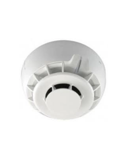
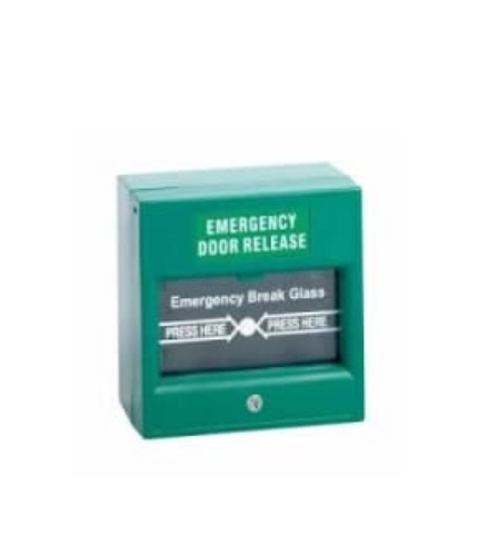
AW-CFP2166-4 is a typical one zone fire alarm control panel which is designed based on EN54 part 2 & 4 standard. It is the heart of the fire automatic alarm system, which can realize centralized control, can supply power to the detectors, manual call point, bell and more. One zone of the panel can match with 20 pieces fire alarm system accessories.
Asenware 2 Zone Fire Alarm Control Panel fire alarm system wire drawing is for reference. Fire alarm control panels are designed to fulfill the requirements of EN54 parts 2 & 4 as well as being easy to install, operate and maintain. Being of modular construction
Asenware 2 Zone Fire Alarm Control Panel specifications
| ITEM | 1Zone panel | 2Zone panel | 4-16 Zone panel | 4-32 Zone panel |
| Photo | ||||
| Model No. | AW-CFP2166-01 | AW-CFP2166-02 | AW-CFP2166-04-16 | AW-CFP2166-04-32 |
| Power specification | ||||
| Mains supply voltage | 110VAC or 240VAC | |||
| Internal power supply | 27.2VDC | |||
| Total output current limited | 500mA @ 240VAC | 500mA @ 240VAC | 3A @ 240VAC | 3A @ 240VAC |
| Main supply monitor for fault | Yes | |||
| Battery protection for low voltage | Yes | |||
| Batteries (default configuration) | 12V2AH*2 | |||
| Detector circuit specification | ||||
| Number of circuit | 1 | 2 | 4-16 | 4-32 |
| Line fault monitor for open circuit | Yes | |||
| Line fault monitor for short circuit | Yes | |||
| Line fault monitor for detector removal | Yes, if End of Line Monitor Unit fitted in place of End of Line Resistor | |||
| End of Line device | 6.8k Ω , 5% tolerance, 0.25W (colour code-blue, grey, red, gold) | |||
| Detector continuity diodes | Silicon 1N4001 or Schottky type (required if End of Line Monitor Unit fitted to give Detector Removal Fault) | |||
| Call point resistor value | 470 to 680 Ω , 0.225 or 0.5 watt | |||
| Maximum number of smoke/heat detectors per zone | 20 (based on a total detector current of 2mA, each detector consuming 100μ A). Note: if End of Line Monitor Unit is fitted, for correct operation maxmum voltage drop must not exceed 12 volts. | |||
| Maximum number of manual call points per zone | No limit | |||
| Sounder circuit specification | ||||
| Number of general circuits | 2 | |||
| End of line resistor value | 6.8k Ω , 5% tolerance, 0.25W (colour code-blue, grey, red, gold) | |||
| Line fault monitor for open circuit | Yes | |||
| Line fault monitor for short circuit | Yes | |||
| Outputs fused AT | 400mA | |||
| Maximum number of bells @ 20mA of each sounder output | 20 | |||
| Fuses | ||||
| Battery fuse | 1.5A F 20mm | |||
| Sounder outputs | 500mA F 20mm | |||
| Fire and fault output | ||||
| Output type | NC and NO relay | |||
| Maximum current | 100mA | |||
| Connection block | ||||
| Largest acceptable conductor size | 2.5mm 2 | |||
| Smallest acceptable conductor size | 0.75mm 2 | |||
| Size and weight | ||||
| Dimensions(mm) | 272*200*70mm | 320*231*90mm | 395X502X124 | 362X565X124 |
| Weight (without batteries) | 4kg | 5kg | 7kg | 8kg |
| Weight (with batteries) | 5.8kg | 6.8kg | 9.6kg | 12.5kg |








Reviews
There are no reviews yet.